Overview
Projects
Specifications
Accessories & Adapters
Technical Drawings
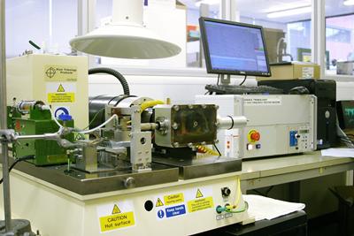
TE 77 High Frequency Friction Machine, manufactured by Phoenix Tribology Ltd., is supplied with its own floor standing bench and with integral control unit incorporating a SUPERSLIM Serial Link Interface Module, which is connected to a host PC with COMPEND 2000 sequence control and data acquisition software installed. The system provides sequence control of load, frequency and temperature plus data acquisition of measured parameters, at both low and high speed.
The moving specimen is mounted in a carrier. A number of different geometries can be accommodated by using a range of simple clamping fixtures. These include point contacts, with a 6 mm ball, line contact with 6 mm diameter cylinder and area contact with a self-aligning button. The specimen is oscillated mechanically against the fixed lower specimen. The mechanical drive comprises a motor driven cam and scotch yoke assembly, providing pure sinusoidal motion. The lower specimen is clamped in either a bath, for lubricated tests, or dry mounting plate.
The stroke length is altered manually by adjusting splined eccentric cams on a splined eccentric shaft. Two fixed cams are provided as standard allowing strokes to be set from 0.4 to 12.5 mm and 12.5 mm to 25 mm
The moving specimen is loaded against the fixed specimen through a lever mechanism actuated by a geared servomotor with in-line spring. The normal force is transmitted directly onto the moving specimen by means of the needle roller cam follower on the carrier head and the running plate on a loading stirrup. A strain gauge transducer is mounted on the lever at a point directly beneath the contact and this measures the applied load.
The piezo electric transducer used to measure the friction force and the output range is set to match expected friction levels in the contact. The maximum friction level is +/- 500 N. A charge amplifier converts the measured force to a proportional voltage. This is followed by a low pass filter, which fixes the upper cut off frequency of the measuring system. This serves to suppress transducer resonance. Final scaling of the signal for voltage output takes place in a second stage amplifier.
The moving specimen carrier is electrically isolated from the drive shaft and therefore from the fixed specimen. This allows a millivolt potential to be applied across the contact using a Lunn-Furey Electrical Contact Resistance Circuit. The voltage signal is taken to a true rms/dc converter amplifier to give a time-smoothed average of the contact potential. Variations in this voltage are indicative of the level of metallic contact, provided that both test specimens are conductors of electricity. This measurement may be used for observing the formation of chemical films from anti-wear and extreme pressure lubricants, the breakdown of non-conducting layers and coatings or the build-up of oxides. The instantaneous value of contact potential is also available for data logging as high speed data.
The TE 77 has PC based sequence programmable control and data acquisition. This is provided by an integrated Serial Link Interface Module and COMPEND 2000 software running on a host PC, operating under Windows. Data is stored to hard disc in standard spread sheet compatible file formats (.csv or .tsv).
The reciprocating tribometer (TE77) is the busiest tribometer in the facility and has been utilised in various student and research projects, as well as numerous consultancy projects.
Projects range from testing of material combinations and coating performance evaluations to tribocorrosion experiment utilising a 3D polymer bath and ceramic balls to minimise unwanted galvanic coupling. The rig was even been used to successful generate the unwanted lubricous organic layer associated with 'leaves on the line' in railway tribology, this required the design and manufacturer of a new rolling head.
The adjustable radius piston ring clamp was utilised during the early stages of development of this head adaptor for studying scuffing in ring-liner contacts.
Projects include:
- Co-Ni-P Electrodeposits for Hard Chrome Replacement - Hard chrome replacement; Nanocrystalline Ni-Co electrodeposits in hcp structure has lower coefficient of friction and wear rate, and Ni-P in amorphous structure provide a better corrosion resistance.
- New generation of protective coatings alternative to hard chrome - hard chromium plating across the European electroplating industry by delivering a suitable substitute, which will be based on nano structured Ni-P and Ni-P composite coatings (with, for example, SiC or BC as reinforcing nanoparticles)
- Luminescent Monitoring for Tribological Coatings - The use of embedded phosphorescence / fluorescence in the coatings has wide applications by monitoring the integrity of coatings
- Scuffing in piston assembly and liner of fired combustion engines - Scuffing is defined as surface damage in a dynamic tribological contact caused by the shearing of cold welded metallic junctions when the lubricant separating the surfaces fails. Once scuffing has occurred the contact usually quickly fails as the severity of the damage rapidly escalates in a matter of seconds. Early detection of scuffing is therefore crucial to understand the causes and events leading to scuffing. The fundamental events leading to scuffing will be investigated by examining the evolution of the surface micro-structure using both contact and non-contact 3D surface profilometery, scanning electron microscopy and nano-indentation techniques. In order for the surface micro-structure to be examined at various instances during scuffing, the project aims to develop a sensor package capable of detecting pre-scuffing as well as major scuffing events.
- Structured Surfaces for Tribological Applications - Texture on various surfaces has been widely studied due to their good tribological performance. The reason for the improved friction and wear properties is still a matter of much debate. It is the goal of this study to investigate the fundamental science of structured (textured) surfaces specifically designed for tribological applications. Laser systems technology will be used to texture tribological surfaces to enhance lubrication, friction and wear performance. Dimples on micro degree are being fabricated, and the performance of them will be tested. Hidden rules are waiting to be explored.
- The Adhesion Rail Riddle - Ensuring Trains Can Brake - Trains rely on traction (adhesion) between the wheels and the railhead to both accelerate and to slow down effectively. Every Autumn, the slippery coating of squished leaves interfere with this adhesion, the result is that the trains cannot brake safely. Trains must therefore travel more slowly, which leads to delays.
- The impact of Friction Modifiers on ZDDP engine oil tribofilms - Modern oil lubricants contain many types of additives, but the most influential on the tribological performance of the lubricant are friction modifiers and antiwear additives (e.g. ZDDP). Because they interact simultaneously with the wear track to generate tribofilms, a careful section is recommended according to the application-specific requirements.
- Tribological behaviour of ultrafine-grained alloys formed by severe plastic deformation - Materials with submicron- or nano-scaled grains produced by severe plastic deformation (SPD) offer new structural and functional properties for innovative products in a wide range of applications. The aims of this study are to understand the effect of SPD processing on wear behaviour of materials, to seek a way to use SPD processing to improve the mechanical properties of materials and their wear resistance.
- Rare earth effect on tribological bronze coatings - Wear on contact surface significantly reduced the lifetime of a component. This leads to economic cost to replacing the component and loss of revenue due to down time. Tribocorrosion resistant coatings are an efficient and economical solution to protect the under laying substrate from wear. These coatings are widely used across many industries such as in manufacturing and automotive. However, these coatings can wear off and exposing the substrate, hence an in-situ wear monitoring of the coating is also desirable to provide early warning about the state of wear. This will allow time for essential maintenance to prevent major damage to the underlying substrates.
- Prolonging the life of machine parts in nuclear applications - The next generation of nuclear power plants will be expected to operate for longer durations and to higher safety standards. Conventional lubrication is not an option in water-based systems, so thin-film coatings such as DLC films
- Influence of contact area on the sliding friction and wear behaviour of an electrochemical jet textured Al-Si alloy
- The effects of substrate dilution on the microstructure and wear resistance of PTA Cu-Al-Fe aluminium bronze coatings
- An electrodeposited Ni-P-WS2 coating with combined super-hydrophobicity and self-lubricating properties
- In-situ stylus profilometer for a high frequency reciprocating tribometer
- Tribological behaviour of an electrochemical jet machined textured Al-Si automotive cylinder liner material
- Self-lubricating Ni-P-MoS2 composite coatings
- Reproducing automotive engine scuffing using a lubricated reciprocating contact
- Ratcheting wear of a cobalt-chromium alloy during reciprocated self-mated dry sliding
- A novel surface texture shape for directional friction control
- The use of anisotropic texturing for control of directional friction
- Scuffing mechanisms of EN-GJS 400-15 spheroidal graphite cast iron against a 52100 bearing steel in a PAO lubricated reciprocating contact
- The monitoring of coating health by in situ luminescent layers
Contact Configurations:
- Ball on Plate (Point Contact)
- Cylinder on Plate (Line Contact)
- Area Contact
- Piston-Ring and Cylinder Liner
Tribometer Specifications:
| Attribute | Range/Value |
|---|---|
| Load Range: | 5 to 1000 N |
| Force Range: | – 500 to 500 N |
| Loading Rate: | 50 N/s |
| Temperature Range: | Ambient to 600°C |
| Heating Power: | 800 W |
| Frequency Range*: | 2 to 50 Hz |
| Stroke Range: | 0.4 to 25 mm |
| Linearity: | 0.50% |
| Maximum velocity | 1 m/s (20 Hz at 25 mm stroke) |
* - there is a 20:1 reduction gearbox that allows frequencies down to 0.1 Hz
Sensors:
| Measurement | Sensor |
|---|---|
| Temperature | k-type thermocouple |
| Contact Potential | 50 mV dc signal |
| Friction Transducer | Piezo-Electric Type |
| Stroke Transducer | Magneto Inductive |
Data Acquisition and software:
| Attribute | Value |
|---|---|
| Low Speed Interface: | Serial Link Interface Module |
| Resolution: | 12 bit |
| Number of Input Channels: | 1 to 8 |
| Number of Output Channels: | 1 to 4 |
| Maximum Data Rate: | 10 Hz |
| High Speed Interface: | USB |
| Resolution: | 16 bit |
| Number of Input Channels: | 6 |
| Maximum Data Rate: | Six channels at 50 kHz |
| Software: | COMPEND 2000 |
Measured and controlled parameters
| Controlled Parameters |
|---|
| Frequency Load Temperature Test Duration |
| Measured Parameters – Low speed data |
| Load Friction (rms) Friction Noise (time smoothed) Contact Potential (time smoothed) Temperature Frequency Number of Cycles Friction Coefficient (derived) |
| Measured Parameters – High speed data |
| Friction (instantaneous) Contact Potential (instantaneous) Stroke Position (instantaneous) |
Services
| Service | Value |
|---|---|
| Electricity: | 220/240 V, single phase, 50/60 Hz, 3.2 kW |
| Installation: | Floor-standing machine |
| Footprint: | 900 mm x 900 mm x 600 mm high, 250 kg |
Three adaptors have been acquired for the TE77 reciprocating tribometer:
This includes a 20:1 reduction gearbox, that bolts on the motor and enable reciprocating frequency from 0.1 Hz up to 2.5 Hz. The gearbox allows smooth motion even at these lower frequencies due to the torque made available by its incorporation. Phoenix Tribology Ltd. part no. TE 77/GB/20
The second is cooling sample holder/plate, this replaces the standard plate with the four cartridge heaters. The replacement is a hollow, channel plate that allows a coolant flow, using a laboratory chiller, temperature below zero can be easily achieve, but icing of components and samples can become an issue, unless dry atmosphere can be employed. Phoenix Tribology Ltd. part no. TE 77/COOLER.
Lastly the Adjustable Radius Piston Ring Clamp -
The ring clamp allows the curvature to be adjusted to allow ring samples to conform with liner samples. The standard clamp can accommodate rings of diameter 90 to 110 mm. The clamp back plate is mounted on a bush, which is mounted in turn on the machines reciprocating shaft. The bush is free to rotate allowing axial alignment between the ring and liner sample. The clamp back plate incorporates two tensioning screws, which engage with the ends of the ring sample; tightening these tensions the ring against the lower side of the bush. The ring is clamped in place by a clamp plate (red). The gap between the two halves of the clamp is adjusted by set screws.
The reciprocating shaft has a hollow bore and connection for an oil feed. The bore communicates via oil-ways in the bush and clamp components to small jets either side of the ring sample. This allows lubricant to be added in small volumes to either side of the ring sample.
A larger clamp has been designed to accommodate rings up to 200 mm diameter. Use of this sized ring requires modification of the lubricant bath to reduce the side wall height.
Below are links to download technical drawings for the TE77 samples.
Note that these are generic drawings and are dependent on the type of testing intended and the material, thus should only be used as a guidance.
Note that the small area contact was designed by Dr. Timothy Kamps