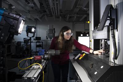
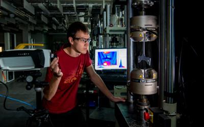
The Testing and Structures Research Laboratory (TSRL) is a multidisciplinary facility that covers a wide range of application areas. The purpose of the facility is to provide the University of Southampton with a state of the art materials and structures testing facility that enable developments in measurement methodologies with a focus on utilising imaging systems to provide information on structural performance. The TSRL provides a major regional and national centre for experimental mechanics research with the primary objective of fostering scholarship and scientific enquiry into the behaviour of materials and structures.
Research carried out in TSRL addresses microstructure-property relationships, material-structure synthesis, design-production coupling and fluid-structure interactions.
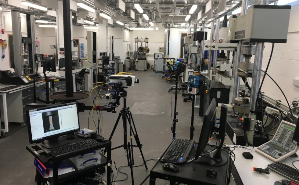
The TSRL contains an extensive range of static, cyclic and high strain rate machines capable of testing a wide range of materials across the loading scales, length scales, temperature scales and strain rates. We also utilise a large number of non-contacting, non-destructive imaging techniques for identifying and quantifying damage and defects within structures and components. There are also facilities for manufacturing composite components.

Typical applications include:

The TSRL contains an extensive range of static, cyclic and high strain rate machines capable of testing a wide range of materials across the loading scales, length scales, temperature scales and strain rates. Equipment includes:

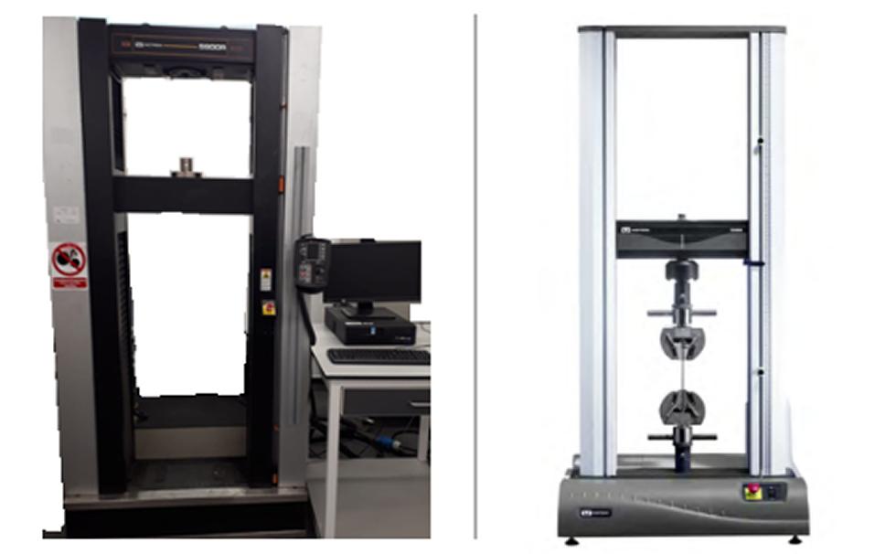
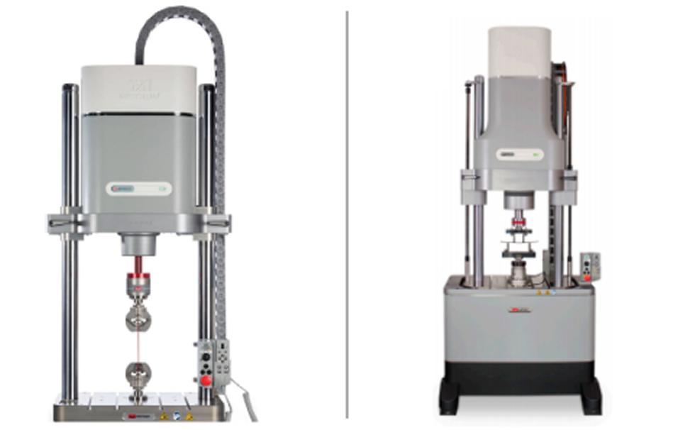
Electromechanical machines for static loading and materials characterisation
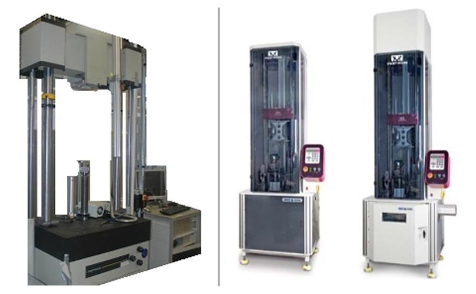
Electrodynamic test machines for static or cyclic testing
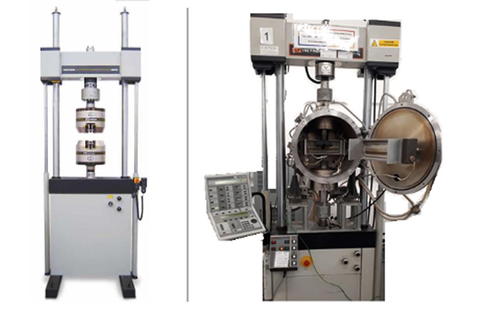
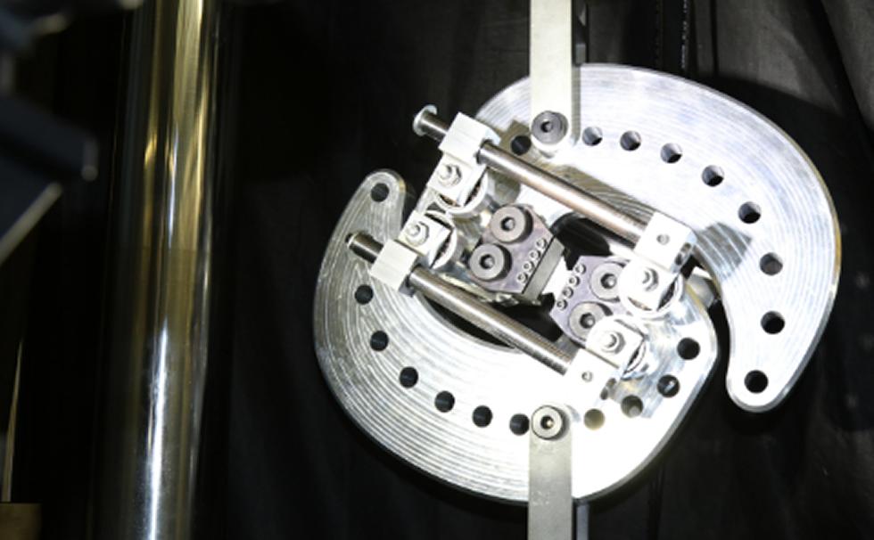
Hydraulic test machines for static or cyclic testing
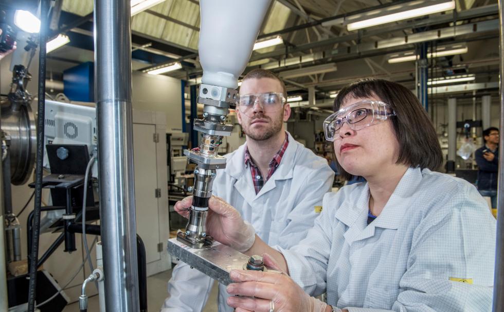
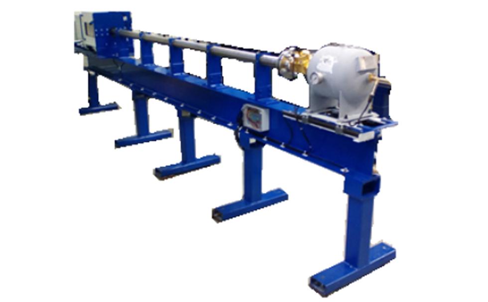
High strain rate test facilities
Strain Measurement Equipment
The TSRL hosts equipment for conducting a large number of non-contacting, non-destructive imaging techniques that can be used for identifying and quantifying damage and defects within structures and components. Techniques include:
More information on the experimental techniques and equipment available is listed below.
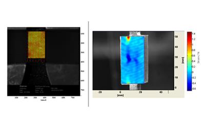
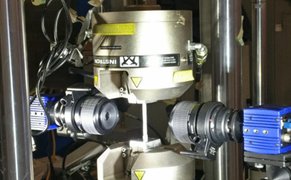
Digital Image Correlation (DIC)
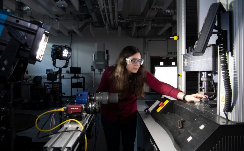
DIC is a non-contact full-field measurement technique capable of obtaining in-plane strains on the surface of a specimen in its 2D configuration and out-of-plane deformation in 3D configuration. Specimens are prepared with a random speckle pattern, usually via printing or using spray paint, and high-resolution images are captured with one or more white light imaging cameras during deformation.
Applications:
High speed imaging
High-speed imaging refers to the ability to collect images at high frame rates. These images may then be used to create a video of an event or used to facilitate measurements. Any of the other imaging techniques listed in this document (DIC, Grid, thermography, TSA, etc) or elsewhere can utilised with high speed imaging. White light imaging can be performed from <1 frame per second up to 5 million frames per second. Infra-red (IR) imaging can be performed from <1 frame per second up to 100,000 frames per second.
Applications:
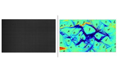
Grid Method
The grid method is a technique suitable for the measurement of in-plane displacement and strain components on specimens undergoing a small deformation. The method is an alternative to Digital Image Correlation (DIC) that uses a regular marking (a grid) as opposed to a random pattern. This enables the use of spatial phase-shifting algorithms to extract displacement fields. As a consequence, the spatial resolution is superior to DIC (typically, one independent displacement data point for a 5×5 pixel subset) for roughly the same displacement resolution.
The grid method features a good compromise between measurement resolution and spatial resolution, thus making it an efficient tool to characterise strain gradients.
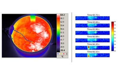
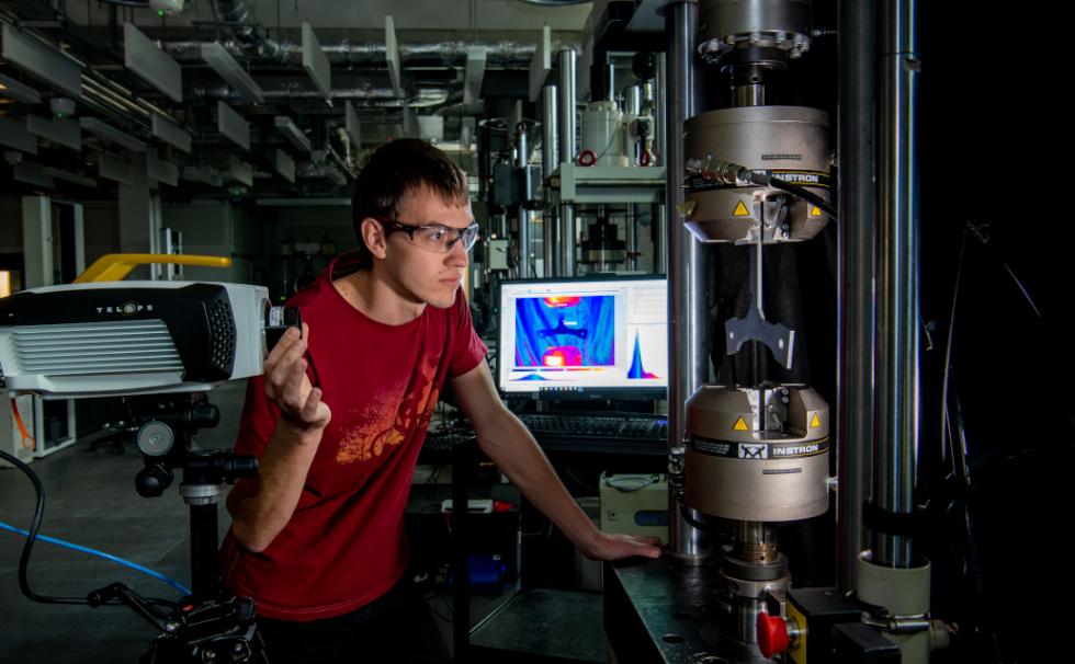
IR Thermography
Infrared thermography (IRT) refers to the general discipline of using infrared (IR) emission from the surface of a material to infer the temperature of the material. IRT is based on Planck’s law that any body at a temperature greater than absolute emits radiation. At ambient temperatures, the peak emission is in the IR spectrum (~ 1μm to 1 mm wavelengths)
Applications:
Any application of temperature measurement with direct line of sight to the object of interest:

Thermoelastic Stress Analysis (TSA)
TSA is an established non-contacting analysis technique that provides full-field stress data over the surface of a cyclically loaded component. It is based on the small temperature changes that occur when a material is subject to a change in elastic strain, generally referred to as the ‘thermoelastic effect’.
The technique is a portable, fast and robust method of obtaining stress information from the surface of a specimen or component.
Applications:
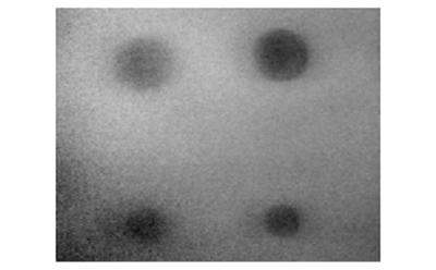
Pulsed and Pulsed-Phase Thermography (PT/PPT)
Pulsed thermography is an active thermographic method. It involves the application of a pulse of heat onto the surface of the sample and uses an IR detector to monitor the surface temperature evolution as the heat front propagates through the material. Where the material below the surface is uniform across the sample the surface temperature will decay uniformly. If there is a volume of differing thermal properties, such as a subsurface defect, then the surface temperature above that defect will vary from the surrounding area.
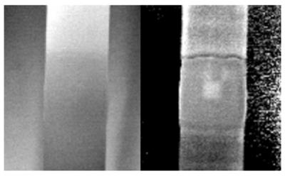
In pulsed thermography the IR thermal data is directly assessed whereas in pulse phase thermography this data is transformed using a fast Fourier transform to obtain phase values. These phase values are less affected by surface effects, such as uneven heating, and so allow deeper probing of the material. Applications include non-destructive evaluation of composite or metallic samples, or of bonded joints for the identification of defects.
Equipment Summary
The following section briefly summarises the imaging equipment
White Light Cameras
High-Speed White Light Cameras
Infra-red imaging systems
The Composite Manufacturing Laboratory enables lay-up using prepreg, hand lay-up and resin infusion techniques. The room comprises work benches for cutting and laminating, an autoclave and ovens for curing, and a freezer for material storage. We routinely manufacture samples and components from carbon fibre, glass fibre and natural fibres.
Dr Andrew Robinson, Principal Experimental Officer, A.Robinson@soton.ac.uk
Testing and Structures Research Laboratory (TSRL)
National Infrastructure Laboratory (N|I|L)
Room 2011, Building 178,
University of Southampton
Boldrewood Innovation Campus, Burgess Road, Southampton, SO16 7QF
In addition to teaching and research activities, the TSRL routinely conducts consultancy and enterprise projects for external clients. If you would like to discuss capabilities and services further, please contact us.