CMOS Gate Array Design Exercise 2001
This year's exercise is to design a circuit to interpret the signals from one axis of a mouse shaft encoder. The circuit will be implemented on a CMOS gate array chip fabricated in the department's own clean room facilities. Two such circuits (along with some glue logic) will be used to construct a complete PS/2 interface for an old style "Atari mouse". The exercise is completed with a demonstration of the "Atari mouse" controlling a Windows 2000 PC via the constructed interface.
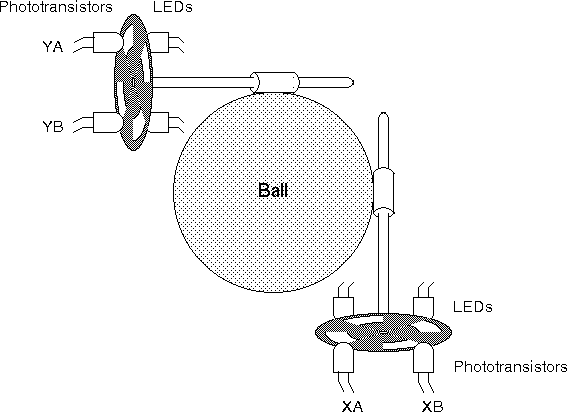
Most mouse computer peripherals use a rolling ball which drives two orthogonally mounted shaft encoders, one for each axis X and Y. The figure below shows this configuration:
Looking in greater detail at a single shaft encoder, we find a rotating disc with holes in it, separating a pair of LEDs from a pair of phototransistors. The LEDs are always on, resulting in pulses of light to the phototransistors as the disc rotates. The figure below shows the mounting position for the phototransistors just above the axis of the disk. In this configuration the signals from the two phototransistors are out of phase such that the signal from A leads the signal from B by 90° as the ball rolls forward and the signal from B leads the signal from A by 90° as the ball rolls backwards.
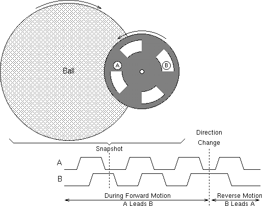
Note that we have a 2 bit Gray code which avoids problems associated with A and B changing at the same time.
In a modern mouse, the signals from the shaft encoder are interpreted causing a counter to increment or decrement as the ball rolls. Whenever possible the count value is transferred to the computer over a serial link (RS232, PS/2 or USB).
Although it is possible to modify the count value every time an edge is detected on either the A or B signal, a much simpler implementation is reached if the count value is only changed when an edge is detected on the A signal. The rest of this document assumes that you employ this strategy.
All PS/2 mice and keyboards use the same underlying protocol for device to host communication; data is encoded in 11 bit frames:

For a simple two or three button mouse, three bytes will be sent to the host to code movement and button positions.
| Bit 7 | Bit 6 | Bit 5 | Bit 4 | Bit 3 | Bit 2 | Bit 1 | Bit 0 | |
|---|---|---|---|---|---|---|---|---|
| Byte 1 | Y overflow | X overflow | Y sign bit | X sign bit | Always 1 | Middle Btn | Right Btn | Left Btn |
| Byte 2 | X Movement | |||||||
| Byte 3 | Y Movement | |||||||
notes
The Atari mouse at the centre of this exercise contains amplifiers to give CMOS compatible 0v and 5v outputs from the phototransistors but doesn't perform any further signal processing, leaving it up to the computer to interpret the signals from the two shaft encoders.
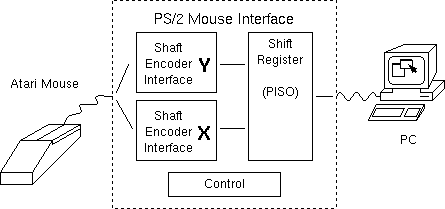
Your task is to build a complete PS/2 mouse interface such that the PC believes it has a standard PS/2 mouse attached to it. A block diagram for the PS/2 Mouse Interface is shown below:
A more detailed system diagram is shown below.
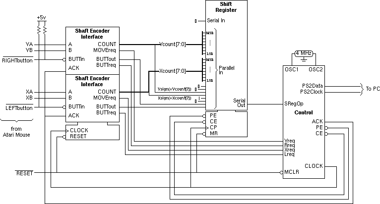
note that various of the shift register inputs are hard-wired
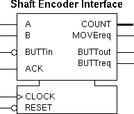
The shaft encoder interface has two inputs, A and B, from the shaft encoder and produces a multibit COUNT value indicating the number of pulses counted in a particular direction.
Since the mouse has two buttons it is convenient for each shaft encoder interface to process the signals from one of the buttons as well as from one of the shaft encoders. The unprocessed button signal is nBUTTin while the processed signal is BUTTout.
In communication with the Control unit the interface has two request outputs. MOVEreq indicates that there have been one or more changes on the A input giving a non-zero COUNT value which is waiting for transfer to the Shift Register while BUTTreq indicates that there has been a change on the BUTTout value which is waiting for transfer to the Shift Register.
An acknowledge signal, ACK, from the Control unit, indicates that transfer to the Shift Register is taking place and should cause the COUNT value to be set to zero and the request outputs to go inactive unless it coincides with further changes on the A and nBUTTin inputs.
In light of the complexity of this year's design it has been decided to make a suggestion on the initial splitting of your circuit into separately testable blocks. All submitted designs should exhibit more testability than described here (more circuit breaks to improve observability and controllability and more test outputs to improve observability only).
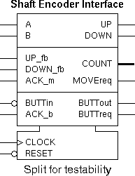
The suggested split is into three blocks. With the exception of common CLOCK and nRESET inputs, the blocks are independent.
During the testing stage, the separate blocks will be reconnected to give the originally specified functionality. Due to the careful choice of signal names, this split circuit will simulate as if it was reconnected thereby assisting with design verification.
Your design for the shaft encoder interface must satisfy the following specification:
All designs must be fully synchronous. Major penalties will be incurred by teams who adopt asynchronous or quasi-synchronous design styles; as well as losing marks you will probably find that your design doesn't work.
A fully synchronous design contains no spurious state elements; no RS flip-flops, no transparent latches and no feedback paths within combinational logic blocks. The only state elements will be the the edge triggered D-types as supplied in the Gate Array library.
Common Inputs
A single clock signal with an active rising edge is common to all D-types. You should not attempt to connect this signal to any gate input or output which is not labelled CLOCK.
A single active-low asynchronous reset signal is common to all D-types, this input is used for initialization only. You should not attempt to connect this signal to any gate input or output which is not labelled nRESET.
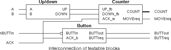
Up/down Module
CMOS compatible outputs from the shaft encoder. Since these signals are asynchronous they should be re-timed (using D-types) before use.
The UP signal will go high for one clock cycle to indicate that the counter should count up, while a single cycle DOWN pulse indicates that the counter should count down.
Counter Module
These are connected externally to the UP & DOWN outputs from the Up/down Module.
Do not make the mistake of connecting these signals to the Up/down Module using tracks on the Gate Array, this will destroy the testability that we are trying to create.
This acknowledge signal from the Control unit will go high for one cycle to indicate that any accumulated COUNT value may be cleared and the MOVEreq signal may be lowered since the COUNT value is being loaded into the shift register for transfer to the PC.
Do not make the mistake of connecting this signal in any way to the nRESET inputs of any D-types. This is a synchronous input indicating that the old value of COUNT should be discarded on the next rising edge of the CLOCK signal.
These outputs give a twos complement value for the number of UP pulses minus the number of DOWN pulses since the last ACK_m pulse. COUNT7 is the most significant bit.
It is not expected that you will implement an eight bit counter, since this would take up a very large part of the Gate Array. It is suggested that you implement one of the following:
A successful two bit counter which avoids overflow and counts up to +1 and down to -1 will receive more marks than an eight bit counter with a really good design that almost works!
This request signal indicates that the shaft encoder interface has detected one or more changes on the signals it receives from the shaft encoder giving a non-zero COUNT value which is ready for transfer to the shift register.
This signal will normally go low when an ACK_m signal is received unless the ACK_m signal coincides with a further change in the shaft encoder signals.
Button Module
This is the output from one of the mouse buttons, pulled high by a resistor when the mouse button is not pressed and forced to ground when the mouse button is pressed. Since this signal is asynchronous it should be re-timed (using a D-type) before use.
This acknowledge signal from the Control unit will go high for one cycle to indicate that the BUTTreq signal may be lowered since the BUTTout value is being loaded into the shift register for transfer to the PC.
This signal indicates the current state of the button to the shift register and hence to the PC. For most implementations, this signal is merely an inverted and re-timed version of nBUTTin.
This request signal indicates there has been a change on the nBUTTout signal which is ready for transfer to the shift register.
This signal will normally go low when an ACK_b signal is received unless the ACK_b signal coincides with a further change in the nBUTTin signal.
In order to clarify the specification, the following diagram illustrates the behaviour of all of signals within the circuit, given a specific set of stimuli from the Atari mouse and the Control unit:
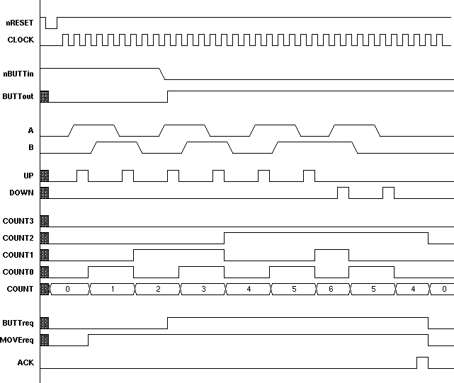
In order for your circuit to meet the specification it is not necessary for it to follow exactly the timing diagram above, this diagram is for a specific implementation.
Nor is it sufficient that your circuit can exactly match the timing diagram, your design must function correctly for all sets of input stimuli.
Iain McNally
24-9-2001