CMOS Gate Array Design Exercise 1998
This year's exercise is to design an encoder or a decoder for an (8,4) Hamming error correcting code.
Simple parity checks can be used to detect errors in a communications link. When an error is discovered the data is discarded and must be re-transmitted.
In certain systems it is desired not only to detect the error but also to correct it without re-transmission. There are a number of different error correcting codes which could be used, but we shall only consider a simple block code which is used by Teletext.
The code has four data bits and four parity bits and is capable of correcting a single error, and detecting certain combinations of multiple errors.
Before transmission, the four bit data word is converted to an eight bit code word by interleaving it with four parity bits.
The four original data bits are b7(=d3), b5(=d2), b3(=d1) and b1(=d0).
The four parity bits are b6, b4, b2 and b0.
     Data Word         Code Word
      d     d      b                b
       3     0      7                0
        0000         0 0 0 1 0 1 0 1
        0001         0 0 0 0 0 0 1 0
        0010         0 1 0 0 1 0 0 1
        0011         0 1 0 1 1 1 1 0
        0100         0 1 1 0 0 1 0 0
        0101         0 1 1 1 0 0 1 1
        0110         0 0 1 1 1 0 0 0
        0111         0 0 1 0 1 1 1 1
        1000         1 1 0 1 0 0 0 0
        1001         1 1 0 0 0 1 1 1
        1010         1 0 0 0 1 1 0 0
        1011         1 0 0 1 1 0 1 1
        1100         1 0 1 0 0 0 0 1
        1101         1 0 1 1 0 1 1 0
        1110         1 1 1 1 1 1 0 1
        1111         1 1 1 0 1 0 1 0
The code word is then transmitted bit serially starting with bit b0.
Detection and correction of errors
When the potentially corrupted data is received, the Syndrome {A,B,C,D} is calculated using the following rules: (n.b. `+' here is modulo 2 addition i.e. exclusive-or)
B = b7 + b3 + b2 + b1
C = b5 + b4 + b3 + b1
D = b7 + b6 + b5 + b4 + b3 + b2 + b1 + b0
The table below shows how the syndrome can be interpreted.
| Syndrome | Inference |
|---|---|
| ABCD | |
| 0000 | Error in b1 |
| 1000 | Error in b3 |
| 0100 | Error in b5 |
| 1100 | Error in b4 |
| 0010 | Error in b7 |
| 1010 | Error in b2 |
| 0110 | Error in b0 |
| 1110 | Error in b6 |
| 0001 | Multiple errors: cannot correct. |
| 1001 | Multiple errors: cannot correct. |
| 0101 | Multiple errors: cannot correct. |
| 1101 | Multiple errors: cannot correct. |
| 0011 | Multiple errors: cannot correct. |
| 1011 | Multiple errors: cannot correct. |
| 0111 | Multiple errors: cannot correct. |
| 1111 | No Error |
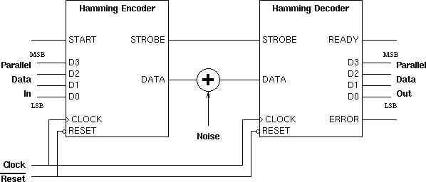
The system when fully completed will be connected as shown:
As mentioned above, you must implement either a Hamming encoder or a Hamming decoder on the ULA. Once the designs have been fabricated, a full system will be built using an encoder from one team and a decoder from another team.
General Information
All designs must be fully synchronous. Major penalties will be incurred by teams who adopt asynchronous or quasi-synchronous design styles; as well as losing marks you will probably find that your design doesn't work.
A fully synchronous design contains no spurious state elements; no RS flip-flops, no transparent latches and no feedback paths within combinational logic blocks. The only state elements will be the the edge triggered D-types as supplied in the ULA library.
A single clock signal with an active rising edge is common to all D-types. You should not attempt to connect this signal to any gate input or output which is not labelled CLOCK.
A single active-low asynchronous reset signal is common to all D-types, this input is used for initialization only. You should not attempt to connect this signal to any gate input or output which is not labelled nRESET.
Encoder Specification
The START input will go high for one cycle when the data is available on the data inputs.
The encoder should not accept two START pulses within any eight cycles as this will corrupt the output stream.
Parallel data inputs. You may assume that these will remain stable for eight clock cycles after the start signal goes high.
Serial data output. Eight bit code words are transmitted bit serially starting with bit b0. When no code word is being transmitted, this output should return to zero.
The STROBE output must go high when bit b0 is output. It is low at all other times.
Decoder Specification
Serial data input.
The STROBE input will go high for one cycle when b0 is available on the serial input.
The READY output must go high for one cycle when the data becomes ready.
Parallel data output. The data need only be valid for the single cycle that the READY signal is high.
Each design should also have an ERROR output which indicates whether an error has been detected during the receipt of data. Such an error is signalled while READY is high and will remain at zero at all other times.
The choice of a circuit for implementation will be one of your most important design decisions for this exercise. In the initial stages you may like to produce outline designs for both an encoder and a decoder. It is certainly possible that one or more of your initial designs will need more than the 67 available gate sites.
In choosing between designs, the key points to consider are:
A good decoder design will be slightly larger than a good encoder design.
A hint for teams who are struggling: A simple implementation of the encoder circuit which doesn't meet the specification for rejecting multiple START signals within eight clock cycles will fit easily onto the ULA and will receive a reasonable mark (if designed and implemented well).
Note that if you chose to relax the specification such as described above you must document this in both your interim and your final reports.
Iain McNally
25-11-98