EX_SEQ

EX_DFFR

EX_XOR2

Integrated Circuit Engineering 2
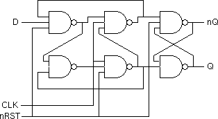
Schematics for the non-leaf cells are shown below:


During this lab you will simulate the schematic using T-Spice to get an idea of the length of time taken to complete the simulation and also to help understand the function of the design. You will then proceed to simulate the layout using advanced techniques:
Here you will be making use of the high simulation speed offered by digital simulation. Such simulations are essential for the verification of medium to large scale digital systems.
Here you will be making use of the advanced capacitance and resistance extraction offered by the Space extraction tool. In this way you can more accurately predict the performance of the final design.
Take a copy of the schematic library W:\TannerLibs\space_lab\sequencer.sdb and open the copy using S-Edit. Using techniques developed in Lab 2, export a netlist EX_SEQ.sp. If you export using the option "Suppress .END in SPICE output" then you can create a file sequencer.sp to control the simulation. When you simulate sequencer.sp the netlist file EX_SEQ.sp is included automatically. This approach is very useful where you want to be able to regenerate the netlist without overwriting the stimulus information.
A copy of sequencer.sp is shown below:
** sequencer.sp
** stimulus for simulation of EX_SEQ cell

** include netlist
.include EX_SEQ.sp

** include MOS models
.include W:\TannerLibs\mAMIs\mAMIs05.md

** define input stimulus
Vdd VDD GND 5V
Vclock CLOCK GND PULSE (0V 5V 9ns 0.2ns 0.2ns 5ns 10ns)
Vnreset nRESET GND PWL (0ns 0V 5ns 0v 5.2ns 5V)

** select output waveforms to view
.print tran v(Out) v(Q2) v(Q1) v(Q0) v(CLOCK) v(nRESET)

** transient analysis
.tran 0.01ns 300ns

** requests fast simulation rather than very accurate simulation
.options fast

.END
Note also that V and s have been used throughout the file to distinguish voltages and times. This information is ignored by T-Spice but should make the stimulus easier for a human to follow.
In this file a PULSE() command has been used to define a clock input with a period of 10ns. The format for the PULSE() command is shown below:


note that any number of time voltage pairs may be specified - the three shown here correspond to those used to define nRESET.
Store a copy of sequencer.sp in the same directory as EX_SEQ.sp. Load your copy of sequencer.sp into T-Spice and simulate it.
Measurements and Results:
Take a copy of the layout library W:\TannerLibs\space_lab\sequencer.tdb and open the copy using L-Edit. Using the techniques described in the document, Switch Level Simulation of L-Edit Designs, extract and simulate the EX_SEQ cell. A stimulus of the form:
    set nRESET = l*1 h*~
    set CLOCK = l*3 (h*2 l*2)*50
will result in a single time step during which reset is active followed
by 50 cycles of the clock. The first 24 time steps of these waveforms are
shown below:

Measurements and Results:
spacesp -spicenet sequencer.gds EX_SEQto extract a new spice netlist EX_SEQ.spice from the GDS II file sequencer.gds that you have created in order to complete the Switch level Simulation.
Copy this new file to the directory in which you have been running your T-Spice simulations and simulate it through a modified version of the file sequencer.sp which includes EX_SEQ.spice in place of EX_SEQ.sp.
Measurements and Results:
Iain McNally
3-4-2003