μ-VIS X-ray Imaging Centre
Multidisciplinary, multiscale, microtomographic volume imaging at Southampton
Example
Sharif Ahmed1, Antonis Zervos1
1Engineering and the Environment, University of Southampton
Over its life cycle, railway ballast undergoes changes to its fabric structure due to train loading and maintenance (e.g. tamping). Understanding these changes and linking them quantitatively to the loading regime has the potential to result in improved designs for new track and more cost-effective maintenance of the existing network. A method has been developed to remove a structure-preserved sample of approximate dimensions 300x300x300mm from below the sleeper railseat.
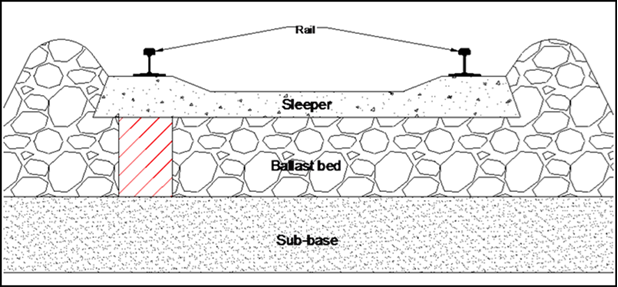
Figure 1: schematic drawing of rail track section. Sampling region is the red, hashed area
Traditionally, mechanical thin-sectioning had to be used as means of internal structure analysis on samples of this size and density. However, the new facilities at the μ-VIS centre are able to penetrate these samples with very good resolution, allowing for true 3 dimensional analysis of the internal structure.
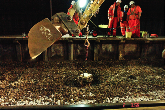
Figure 2: sampling in progress
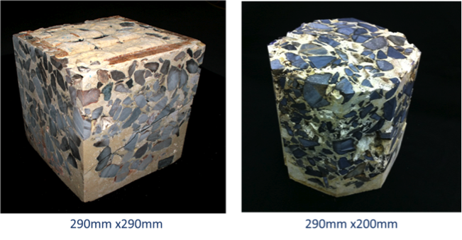
Figure 3: (left) sample initially shaped as a cuboid; (right) sample reshaped to an octagonal prism to optimise beam penetration
In order to quantify the internal structure of any granular media one must describe the particle orientation, void/pore network and contact points in 3D space. Computed Tomography (CT) provides the only means of carrying out this form of quantitative analyses non-destructively.
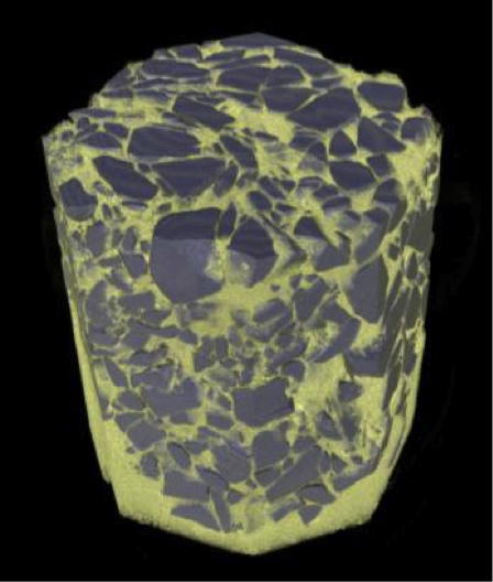
Figure 4: volume rendering of resin (yellow) occupying the void space and granite ballast (blue-grey)
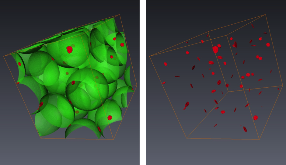
Figure 5: contact patches with a sample of glass ballantini
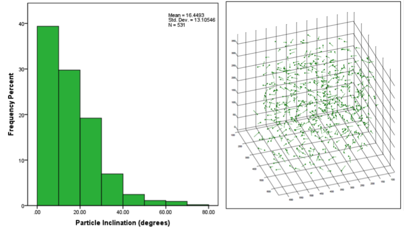
Figure 6: ballast particle orientation in 3D space