Overview
Recent Improvements
Projects
Specifications
Technical Drawings
The slurry jet erosion rig, is driven by a Crest Pumps PPM multistage mechanical seal centrifugal plastic pump, the rig is capable of erosion velocities of up to 30 m/s and typically with a sand slurry concentration of 2%, but many other erodent(s) and concentrations have been employed.
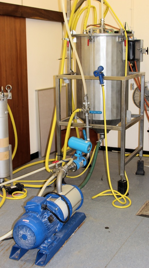
The rig is undergoing an upgrade and a number of improvements have either been implemented or are in the process of being implemented this includes:
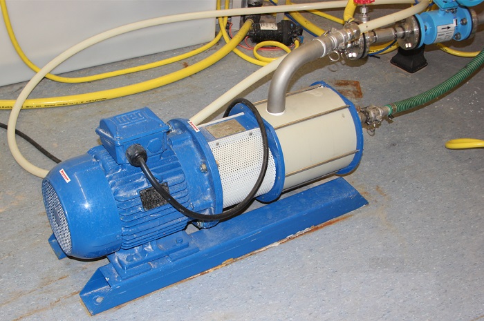
- Replacement of the old pump with a higher duty pump, the aging pump was deteriorating leading to unusually high volume replacement of vital components, mainly the rotor and stator. The new pump is a slower but similar/higher volume flow rates, which should reduce the wear rate.
- A new electromagnetic flow meter has been acquired.
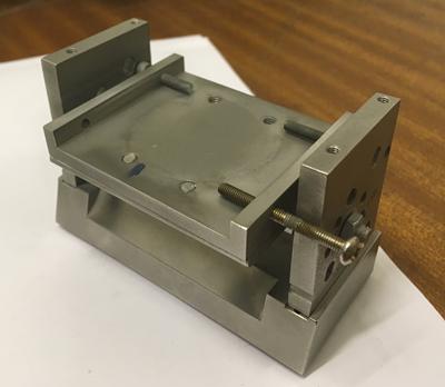
- A sample holder has been designed and manufactured, the latter by Safire and Associates, more details are below.
- A new test chamber has been manufactured, this chamber will be able to 200 litre of slurry, a large increase on the current 9 litres, this was to enable use of the larger 11kW pump. The larger pump had issues with heating the slurry, resulting at 20°C in as little as 30 minutes. The large volume flow rate also produced issues with foaming by introducing large volumes of air into the slurry and not enough settling time for it to come out.
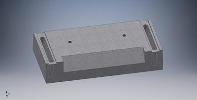
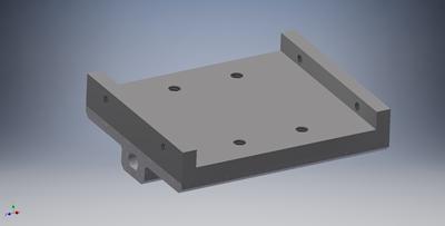
The sample holder had several design iterations before settling on the current design, which combines simplicity with innovation. Simplicity is essential as complexity in such an erosive environment often creates later complications.
The base has a slope front edge with threaded holes on top and below for a sheet of rubber to affix over the edge during low angle erosion. The base also has two slots with two holes on each side so the supports can be located correctly each time.
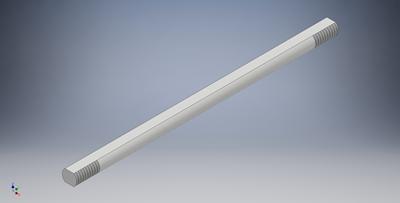
Between the supports is a bar, circular but with two flats on top and bottom. This fixes the orientation (angle of impingement) of the holding plate as it slots into a special designed groove in the holding plate.
The holding plate itself is composed of two parts and together by four bolts. The top part is interchangeable for the two sizes of erosion samples (50 × 50 mm and 50 × 25 mm). It is also interchangeable as it is a long-term replaceable part as the sides that house with the tightening bolts erode of time. The base also has a couple of threaded holes for location of the plate relative to the sides.
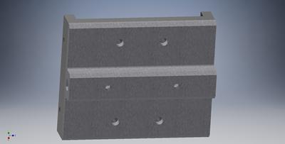
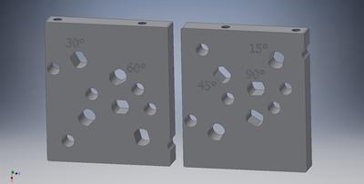
Lastly and where most of the innovation is, the supports. These are identical and also reversible. The sides have slotted holes which match the shape of the support bar, as well as some circular holes. These slotted holes fix the bar and thus sample at a fixed angle (15°, 30°, 45°, 60° and 90°), all the required erosion angles. The angled slots are at different positions, both vertically and horizontally. The reason for this is to position the middle of the sample, when located in holder, directly below the nozzle and at the same distance (commonly referred to as 'stand-off distance'). Due to the number of slots it was necessary to make the supports reversible to accommodate them so they did not overlap. The additional circular holes are large clearance for the bolts holding the sample in place when the holding plate is inclined (i.e. anything not 90°). Lastly by the angled slots there is a stamp mark to indicate which angle they are.
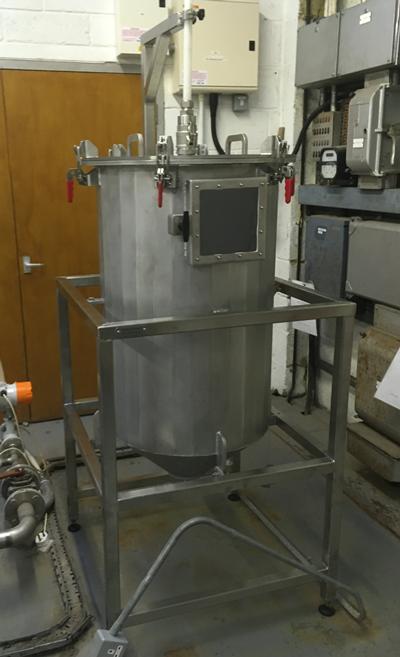
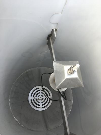
The new chamber has been installed, the chamber and frame are stainless steel for corrosion resistance in this working environment. The main body is made from folded and welded sheet/plate that give it this polygon shape. The lid is designed for large access, while the side panel provides operational usage (changing samples). The lid holds the nozzle, which is held in a specially designed holder that can slide up and down to adjust the stand-off distance (between nozzle and sample). On the inside there is a specially designed nylon sheet liner with a jigsaw interlocking. The liner will protect the sides from erosion damage. There is also a drain cover at the bottom to prevent accidental object (tool and sample) entrainment into the recirculation system.
The slurry jet has been used for research and consultancy project examining the erosion resistance of hard coating and materials.
Erosion rig Specifications:
| Attribute | Range/Value |
|---|---|
| Impact Velocity: | 20 to 100 m/s* |
| Impact Angles: |
15°, 30°, 45°, 60°, 90° |
| Erodent type*: |
silica sand, alumina |
| Erodent size: | sub 100 µm to 2 mm |
* - these are the commonly used erodents, but others can be incorporated.
There are a range of sieves for producing narrower distribution of particle sizes and these include:
- 710 µm
- 500 µm
- 355 µm
- 250 µm
- 180 µm
- 125 µm
- 106 µm
- 63 µm
- 45 µm
- 38 µm
Below are links to download technical drawings for the erosion samples.
Note that these are generic drawings and are dependent on the type of testing intended and the material, thus should only be used as a guidance.
Useful Downloads
Need the software?PDF Reader