S. Rosini1, M. N. Mavrogordato1,2, I. Sinclair1,2, S. M. Spearing1
University of Southampton
1. Engineering Materials Group, Faculty of Engineering and the Environment
2. μ-VIS X-Ray Imaging Centre, Faculty of Engineering and the Environment
Background
Carbon fibre reinforced polymers (CFRPs) are a critical structural material for aerospace engineering. The lack of composites predictive models is the cause of current overdesigned composite applications.
A deep understanding of how carbon fibre composites fail would improve these tools and allow a much wider use in more applications. High resolution X-ray computed tomography (CT) is performed to investigate the fibre break accumulation mechanisms in untoughened aerospace grade carbon/epoxy coupons under quasi-static load. This study provides information on the accumulation and interaction of fibre breaks in simple double-notched coupons, where groups of interacting fibre breaks (clusters) are observed and quantified. Aim of the study is to provide experimental evidence to the modelling community to further improve the existing predictive models for continuous carbon fibre/epoxy reinforced composites.
Role of µCT
High resolution X-ray micro-focus CT in combination with Synchrotron CT has a key role in understanding the process of damage accumulation in CFRPs. Fibre failure is one of the main mechanisms of final failure for this class of materials and a limiting factor of tensile strength. Fibre failure is a phenomenon happening at a micro-scale; a micrometer analysis is then essential to observe the appearance and evolution of this kind of damage. High resolution X-ray CT is a data-rich technique and allows one to analyse the fibre break accumulation mechanism from low to high strains, showing the interactions between damage and microstructure.
Figures
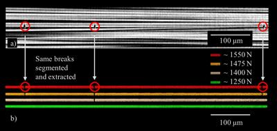
Figure 1 - Time series of fibre breaks within an individual fibre as a function of increasing load. a) CT image showing 3 breaks within the field of view along a fibre; b) the same fibre as identified in (a) segmented and extracted from four different load steps.
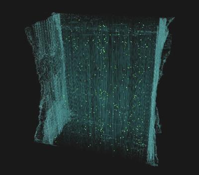
Figure 2 - 3D segmentation of the fibre breaks (green) of an in situ tensile tested CFRP sample at 99% UTS, using VGStudioMAXTM.
Acknowledgements
The authors would like to acknowledge the European Synchrotron Radiation Facility for provision of synchrotron radiation facilities and would like to thank Dr Lukas Helfen and Ms Elodie Boller for assistance in using beamline ID19. The authors also gratefully acknowledge Mitsubishi Chemical Co. for materials supply and funding.
-